
Wiring diagrams: eating spaghetti for breakfast
- Aug 1, 2025
- 5 min read
For many engineers who haven't had formal training in controls design, wiring diagrams can look pretty daunting. The aim of this blog post is to give a basic outline so that you can take what might look like a page of spaghetti and be able to explain what's in front of you. In fact if you spend a bit of time reading this then you might even be able to eat it for breakfast...
Let's get the big one out of the way: the wiring diagram isn't a diagram of what wires are run inside the control panel. If you try and trace wires and expect them to match what's on the wiring diagram you're going to start getting confused. Here's a simple demonstration of that:
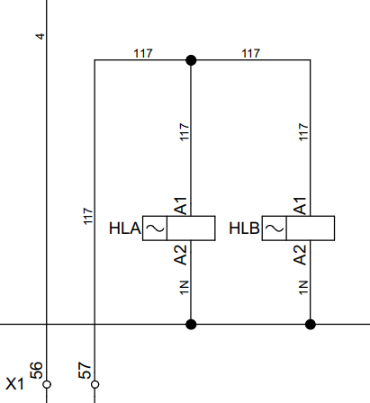
How many wires in that panel are numbered 117? The answer is, probably two - but not definitely. And HLA may be nowhere near HLB.
Symbols and styles vary from one diagram to the next. The international standard is IEC 61082-1, and the British-adopted version is BS EN 61082-1. But in the real world there's a wide variety of ways of drawing the same thing. However we'll cover some of the most common symbols here, which are all taken from our own wiring diagrams.

A 3-pole isolator used where the incoming main comes into the control panel. In this case it is for a 400V 3-phase supply of up to 25A, and would be interlocked with a handle on the door so that the control panel can't be opened with the isolator turned on.

A 2-pole MCB, usually used to supply a live and neutral on a 230V single phase circuit. This one is a 4A C-curve MCB.

A transformer, for converting AC power from one voltage to another. This one has several options on the primary (incoming) side, but the 240V is what's being used. On the secondary (outgoing) side it can be used for 12V or 24V, 24V is what's in use.

A pilot lamp, sometimes referred to as an indicator light, which is mounted on the panel door and shows that power is on to the panel. Sometimes the drawing will also state the colour of the lamp, but not always.
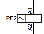
This shows the wires going to the coil of a relay. The two terminals they connect to are labelled 'A1' and 'A2', which is typical for the terminals either side of the relay coil. In this case it's an AC relay as shown by the wavy line on the left. Note that timers often use a similar symbol, although many have an additional 'trigger' input.

This is a relay contact, which shows the wires going through the relay (as opposed to the wires going to the coil, which turn the relay on and off). This shows a 'changeover' contact, where you have the feed coming in the top (on terminal 9) and then both a normally open (terminal 5) and normally closed (terminal 1) on the other side. The '4.1' refers to where you can find the relay coil on the wiring diagram, helpful for cross referencing.

A 3-position switch. This will usually be mounted on the door, you can see the three contacts are linked together with a dotted line and the symbol on the left represents the switch.
There's of course many more, but that's a good start.
The lines that connect one component to the next show which points have the same 'potential'. In the real world that means they're physically connected together somehow (usually with wires), so if there's voltage on any part of that wire then there's voltage on all of it. The circles show where they are connected - if there's no circle then it means the lines just happen to cross on the page and aren't linked together. Each potential should be numbered, and then every where in the panel will have that number on it. Every time a potential goes through something which could alter it it's assigned a new number.
Now to bring some of that together with an example:
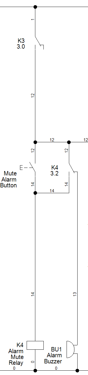
At the top you can see the potential numbered '1' going across this section, which has been connected on to. This is likely to represent permanent power on the controls circuit.
It then goes through a normally open contact on relay K3, which as you can see from some of the other naming is likely to be an alarm.
Assuming K3 is energised so that contact is closed, the power will flow down to potential '12'. This will get as far as the mute pushbutton but (if it's not being pressed) no further as it's normally open. It will however go through the normally closed contact on K4 and down to the buzzer. Note that the buzzer has power on one side (potential 13) and neutral/0V on the other side.
When the mute button is pushed it allows power through to the coil on relay K4. This will change the state of the K4 relay contact, which will stop power going to the buzzer and instead send it back to its own coil. This will have the affect of stopping the buzzer from sounding, and also keep K4 energised even after the button has been let go.
With K4 holding itself on the buzzer will not sound again until either the power to the panel is turned off and on again, or the alarm (K3) stops and then starts again.
While we're looking at the example there's a couple of new symbols to check out. The mute button is a pushbutton, likely mounted on the door, with a single normally open contact block on it. The buzzer is a sounder which is also most likely mounted on the door.
You'll notice that there's no way of seeing from the wiring diagram where the actual component is located. Sometimes you'll see a box around anything which is on the door, but not always. However it should make clear what's in the panel and what is outside of it. For example if the panel is powering a pump then the pump's terminal numbers may be shown on the drawing, but should show that it's not part of the panel.
This post has covered the basics of the wiring diagram. Included with it is usually a number of other documents, such as:
Cabinet layout (often referred to as a 'General Arrangement', or GA)
Terminal list (a summary list with all the terminals for connecting field wiring to)
MCB schedule (a summary list with all of the circuits and the MCB which supplies them)
Bill of Materials (or BOM)
These are all useful, but by themselves don't tell you how the control panel works. Only the wiring diagram does that. And if there's a PLC/controller in the panel, which runs its own logic, then you have no way of knowing exactly how the control panels, so good luck!


